您如何跟上现代船舶设计日益复杂的步伐?
造船厂需要能够有效地处理大量数据的设计和管理系统,同时能够设计整个级别的船舶。通过数字孪生消除不同解决方案的障碍,以改善流程和效率,实现多学科海洋设计软件方法。
利用端到端的多学科船舶工程和制造解决方案,将团队与无缝、集成的信息流连接起来,为所有海事应用提供协作和并行设计。

通过涵盖设计、验证和制造的多学科解决方案,在海洋工程生命周期的每个阶段统一利益相关者。
随着海运业需要更先进和可持续的船舶,不同且互不关联的解决方案阻碍了设计团队的高效设计。设计团队需要单一事实来源和集成的工作流程,将参与船舶设计的所有工程团队联系起来。了解其他公司如何从全面的海洋工程解决方案中获益。
通过自动化工作流程和计算流体动力学(Bar Technologies)降低油耗。
实施 PLM 解决方案时,开发时间最多可缩短 50% (Tech Clarity)。
利用 3D 仿真工具将测试时间缩短 20%。通过虚拟原型设计(Brabant Engineering)缩短测试周期并节省资金。
您如何跟上现代船舶设计日益复杂的步伐?
造船厂需要能够有效地处理大量数据的设计和管理系统,同时能够设计整个级别的船舶。通过数字孪生消除不同解决方案的障碍,以改善流程和效率,实现多学科海洋设计软件方法。
利用端到端的多学科船舶工程和制造解决方案,将团队与无缝、集成的信息流连接起来,为所有海事应用提供协作和并行设计。
在船舶设计和生产过程的任何阶段,利用数字孪生来提高所有船舶设计的船舶设计速度。
借助海洋工程,通过船舶设计阶段的无缝信息流加快您的设计项目,并使您的设计师能够在端到端设计过程中快速搜索、检索和协作。
在每个阶段继续探索多学科能力。
我们为海洋工程提供众多种类的按需培训课程,以及向个人和公司开放的预先安排的课程。我们的海洋工程解决方案服务包括实施和调试支持、维护和现场支持。
安装后,我们在调试期间提供可选的技术支持,无论是在您的工厂还是远程,以根据每个造船厂的程序和方法准备解决方案。
我们提供维护服务,包括海洋工程解决方案的年度更新和新功能,以及通过互联网、电话和电子邮件提供的永久技术支持。
根据要求,我们还提供现场技术支持,以便您可以增强知识,培养理想操作技能,并习惯最近推出的改进和新功能。
海事产业在遵守可持续发展法规方面承受着越来越大的压力,船舶制造商可借助海洋工程软件的力量将创新型推进系统和替代燃料源融入新的船舶工程设计之中。这些解决方案为船舶制造商提供了所需的工具,既能满足可持续航运日益增长的需求,同时又能保持效率并降低成本。
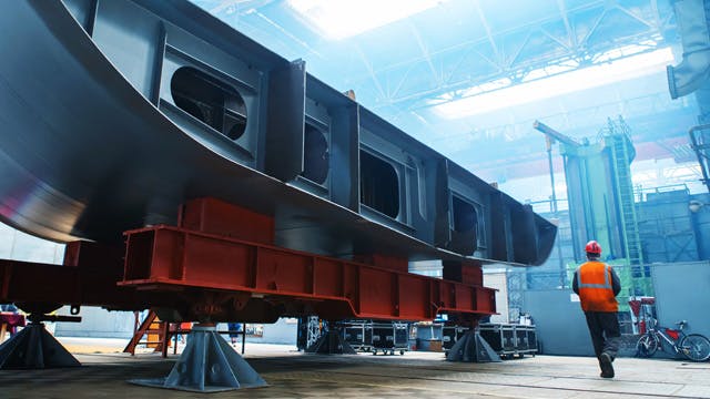
多学科设计软件将造船所需的不同工程学科结合在一起,通过一套集成的产品设计、验证、制造、协作和可视化工具,在一个统一的解决方案中消除创新障碍。
钢结构、机械、管道、暖通空调、二次钢和电气电缆都在设计环境中捕获,使这些学科的用户能够同时协同工作。这有助于更快地交付设计,并减少设计过程后期的跨学科集成问题。由各个学科创作的数据可以同时实时可视化。
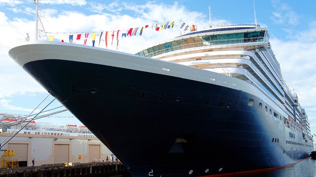
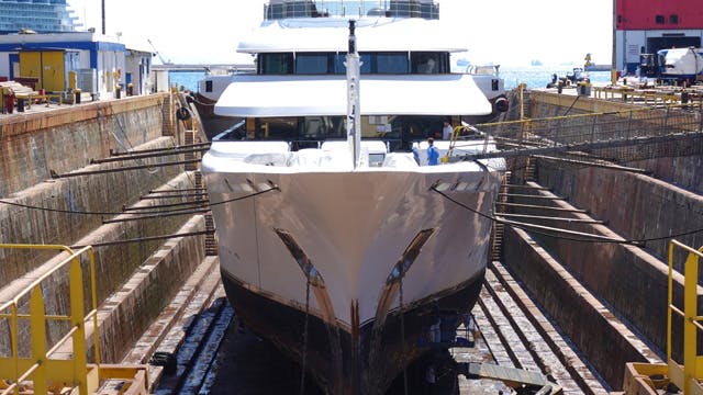
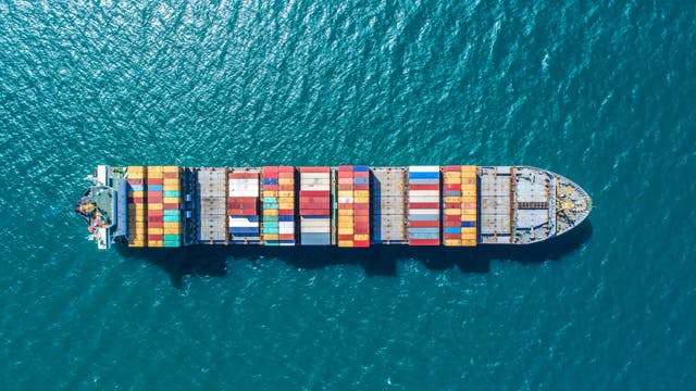
我们的集成式设计和海洋工程解决方案可以帮助船舶制造商设计包括商船、军舰和游艇在内的各式船舶。