
Tecnomatix 数字化制造软件
立即实现制造和流程的数字化,将您的创新理念——从汽车、飞机和医疗器械到电子产品、消费品和啤酒,转化为客户的变革性产品。
为何选择 Tecnomatix?
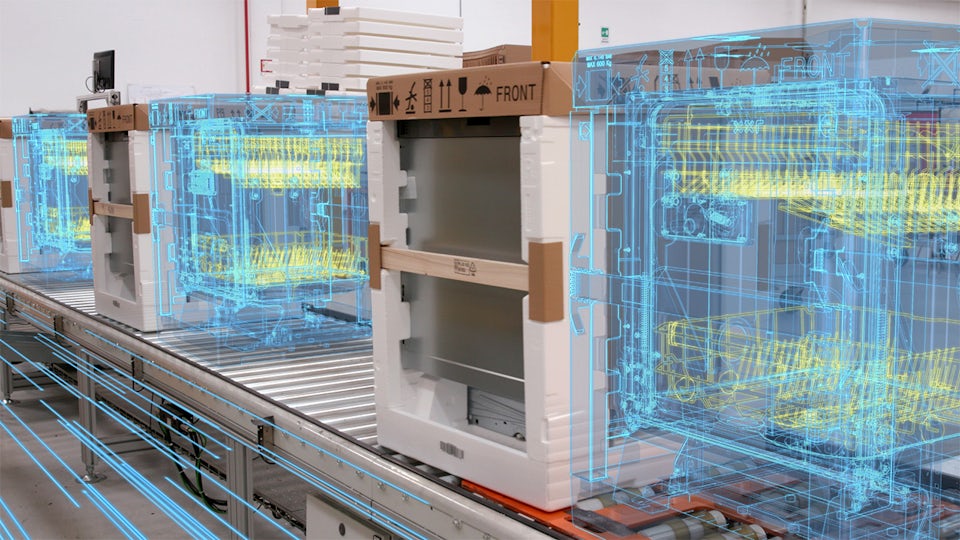
构建数字孪生
对制造流程(包括机器人、自动化、物料搬运系统和人员)的全面数字孪生进行建模、仿真和优化,以提高业务绩效。
提高灵活性
在自动化或手动生产过程中使用仿真和优化来评估和实施先进的制造技术、设备和操作,提高制造灵活性。
加快创新
使用逼真的沉浸式高保真环境以及基于物理的建模、仿真和优化工具,加速创新。
以人为本的制造方式
我们如何进入海底和外太空?我们如何保持安全和互联?以人为本的制造方式。
以人为本的制造可帮助您立即将未来的创新转化为变革性产品。它利用先进的机器人技术和人工智能等突破性技术,让自组织工厂成为现实。了解未来的制造业。
探索 Tecnomatix 功能
利用数字化制造来改善业务,实现未来可持续发展。


在 Tecnomatix 博客上获取近期新闻
案例分析
伊莱克斯
Case Study
Teamcenter, Simcenter and Tecnomatix help reduce development time by 20 to 30 percent
公司:Electrolux
行业:消费品和零售行业
位置:Stockholm, Sweden
Siemens 软件:Simcenter 3D Solutions, Teamcenter, Tecnomatix


