A woman looking at Simcenter CAD-embedded CFD simulation on a couple of screens.

Simcenter

CAD-embedded CFD simulation

Computational fluid dynamic (CFD) simulation in computer-aided design (CAD) for designers to analysts.

Shorten development timelines

Perform CFD simulation earlier using fully CAD-embedded CFD software for designers to analysts. Eliminate typical analysis workflow overheads to shorten development using fluid flow and heat transfer simulation on native CAD geometry in NX, Solid Edge, CATIA and Creo.

CAD-embedded CFD simulation capabilities

CFD simulation in the CAD interface

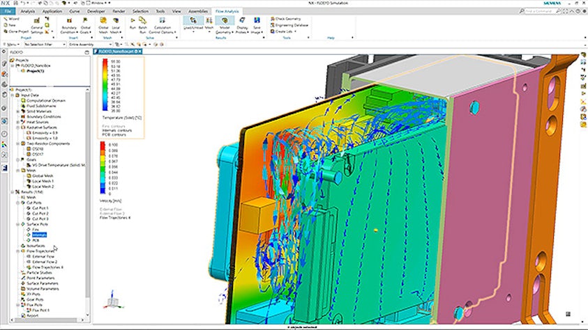
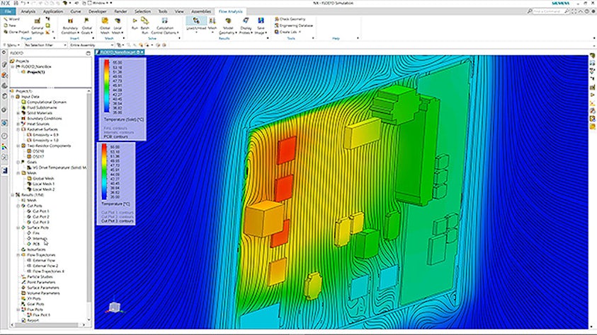
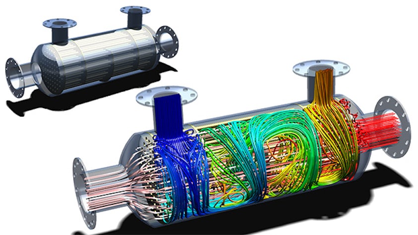
Fully CAD-embedded CFD simulation enables design engineers to analysts to conduct fluid flow simulation and evaluate heat transfer in the CAD design environment, with an intuitive interface and using CAD geometry directly. This eliminates the time overhead of CAD data translation, eliminates geometry simplification or preparation for CFD steps, and allows engineers to conduct multiple design studies and evaluate results. Design engineers therefore can focus on how modifications to geometry or operating boundary conditions influence performance. As simulation results are available earlier in development, informed decisions can be made.

CAD simulation being created

Frontload CFD simulation

Simulation frontloading is the process of moving simulation earlier in development where it can most impact design performance, help to reduce costs in prototyping and avoid late-stage design rework. Frontloading CFD simulation refers to the practice of moving computational fluid dynamics simulation early into the design process and being placed into the hands of design engineers. This democratization of CFD simulation using CAD-embedded CFD means design engineers can evaluate fluid flow and thermal performance, examine trends and dismiss less desirable design options to improve product design. Frontloading CFD as a methodology can shorten overall development by making the simulation process many orders of magnitude faster. It allows engineers to optimize product performance and reliability, and reduce physical prototyping and development costs.

Flowchart showing the methods, processes and IT solutions in the early development phase

CFD user experience for designers

To integrate CFD into the CAD design environment, it must be intuitive to mechanical and design engineers who use CAD regularly. Whether you use CFD simulation regularly or infrequently, it is beneficial to have an intuitive, familiar environment, menus, selections and logical workflow steps. It is highly advantageous to leverage a solution that combines pre-processing, CFD simulation set up, solution monitoring and results post-processing and evaluation all within the CAD design environment. To enable ease of use and consistency, intelligent automation is a key enabler for design engineers. This can take the form of analysis wizards to guide users through the simulation set up, automatic meshing, and real-time feedback about simulation solution progress. Design engineers can realize value in quick and clear results in the form of plots, tables and reports, so generating these simple without additional steps.

A visual of Simcenter software.

Automated meshing for CAD-embedded CFD

Intelligent pre-processing and automation can help design engineers to analysts be more productive with a CAD-embedded CFD tool. Working in the CAD environment, fast automatic leak detection, methods to quickly seal geometry and automatic fluid volume detection are desirable examples of intelligent automation that can speed up any CFD simulation process. Automated meshing technology designed to work directly with CAD geometry and handle complex or variable quality geometry without the need to simplify CAD models is recognized as a key to faster, accurate CFD for the design environment. There is proven value in stable, robust cartesian immersed boundary gridding methods whereby automatic mesh refinement is based on geometry features, and can be combined with solution adaptive refinement for regions of higher flow and thermal gradients.

When meshing is possible to automate and reduce from days to hours or from hours to minutes, then it is providing a true step change for shorter CFD analysis compared to typical CFD software. Intelligent automation coupled with innovative automated meshing technology and ease of use allows design engineers and non-specialists to reliably conduct CFD analyses early in the design process. When combined with localized meshing controls and advanced options, CAD-embedded CFD also provides a fast and efficient alternative approach for experienced analysts to tackle a wide range of typical CFD problems.

On-screen image of a CAD-embedded CFD tool

CFD using CAD geometry without simplification

The benefits of CAD-embedded CFD that directly uses native CAD geometry without the need for simplification, is that pre-processing and time spent preparing CAD for CFD is eliminated or minimized. This also eliminates errors in translation of information between teams.

Working directly with CAD geometry for analysis and evaluating results and design options means that downstream design function connectivity is enhanced through quick communication of CAD geometry from an optimized design.

Two CAD created images of a machine part - one with its metalic skin, the other a cutaway showing a heat map of airflow through it

CFD simulation-driven design optimization in CAD

When design engineers can directly perform CFD simulation earlier and more often, they can make better design decisions with confidence. An ability to easily compare results from different model configurations, making changes in geometry through to evaluating more operating conditions, brings the power of simulation insight closer to design. Engineers with access to easily set up parametric studies, what if scenario exploration to advanced design of experiments capabilities, can more fully explore the design space to deliver better product performance and reliability within project deadlines.

The concurrent CAD model of an optimal design selected using simulation can be immediately communicated to other engineering functions such as manufacturing. CAD-embedded CFD enables fluid dynamics simulation-driven design to be integrated into the overall product lifecycle management process.

Multiple iterations of a single part as seen in a CAD simulation