A circuit board designed in NX CAD.

PCB systems

Electromechanical design

A design solution that enables ECAD, MCAD and PCB engineers and controls systems to collaborate on a single, unified platform to get the right products to market faster and to exceed customer expectations.

On-demand webinar

Seamless ECAD-MCAD collaboration for electronic systems

Learn more about ECAD-MCAD co-design, combining the workflows into one platform.

A 3D rendering of the printed circuit board (PCB) of an insulin pump designed in NX.

Mechanical - electrical design

Employ a unified solution for every phase of electromechanical design with NX. Real-time information sharing between electrical, mechanical and control systems designers is essential to delivering innovative, high-quality products on time and under budget.

Data exchange accelerates design, reduces errors

Coordinate and synchronize your mechanical and electrical design teams and systems using PCB Exchange. Readily share engineering data and easily track and manage changes to enhance collaboration. Accelerate design and reduce errors by reducing the time spent on tracking, converting and re-entering information.

A graphic of a circuit board.

Two-way transfer of PCB data

Transfer schematic and component data—once the printed circuit board (PCB) is designed in the ECAD system—back to NX and automatically create an accurate 3D assembly model of the board for use in the mechanical design. As the design progresses, you can use PCB Exchange to compare board versions and update the board model automatically. Detailed reporting of the design changes streamlines communication across disciplines.

The image shows the collaboration and synchronization of PCB data between ECAD Expedition and MCAD NX.

Integration with electrical design tools

Leverage NX PCB Exchange to interface with major PCB design systems via standard interchange formats and vendor-specific data exchange formats. You can use NX Flexible Printed Circuit Design to create rigid or flexible PCBs in the context of an assembly model and then easily transfer board outlines, keep-in and keep-out regions and other data to the PCB design system for board layout.

Mechanical - electronics design

It’s no secret that products today are increasingly complex with many, if not most, reliant on integrated electronics. An efficient ECAD-MCAD co-design process enables you to eliminate costly electromechanical issues during new product development by giving a holistic view.

ECAD and MCAD collaboration

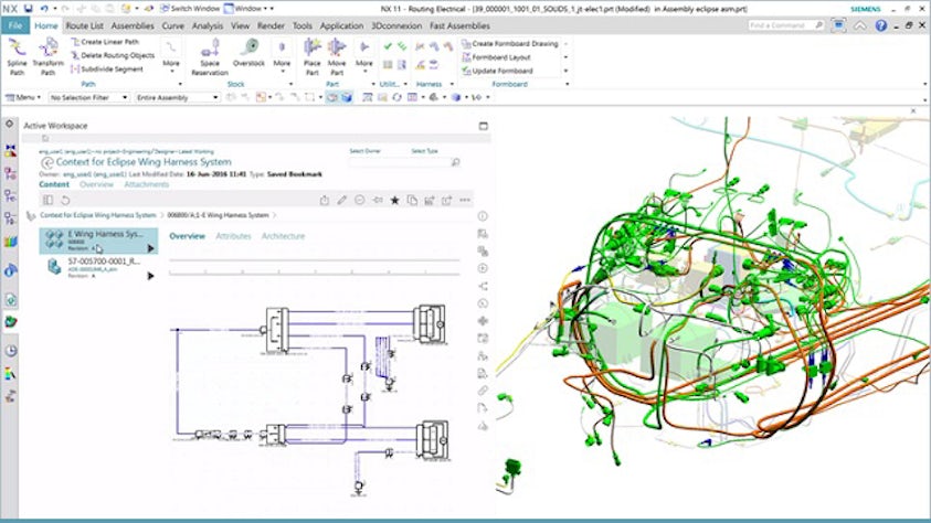
Manage and support design collaboration. During design product development, there is a need to communicate between different applications to keep the digital twin or seamless digital thread as a single point of truth.

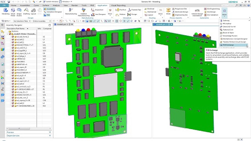
Full rigid-flex collaboration is possible, giving both MCAD and ECAD domains the same view of the PCB in both the flat and the formed states. Not only can you collaborate, but you can review and validate that information. You can then push that data into the manufacturing realm, where you can reread that data to NX as the manufacturing output is created. This can be used for jig manufacture, test equipment or just downstream documentation.

Integration with Capital and Siemens Xpedition

Access united electrical, mechanical and control systems in a truly multidisciplinary platform. By linking the electrical schematics and the 3D model, called cross-probing, designers of wiring diagrams and harness configurations can work closely together to prevent costly and time-consuming rework due to errors.

The image shows the design work of a wire harness in the only true multidisciplinary platform on the market today, linking the electrical schematics and the 3D model.
White paper

ECAD-MCAD co-design leads to first-pass success

Learn how to minimize costly design iterations, reduce product development costs and speed time to market with an integrated ECAD-MCAD solution.

The image shows a final product in the for of a Industrial Embedded PC (Siemens SIMATIC IPC227E)
Case study

Design Automation Associates

Automated circuit board vibration analysis reduces errors and results in 100x faster process
Case Study

Automatyczna analiza drgań na płytce PCB redukuje liczbę błędów i stukrotnie przyspiesza pracę

Firma:Design Automation Associates

Lokalizacja:Suffield, Connecticut, United States

Siemens Software:NX, Simcenter 3D Solutions