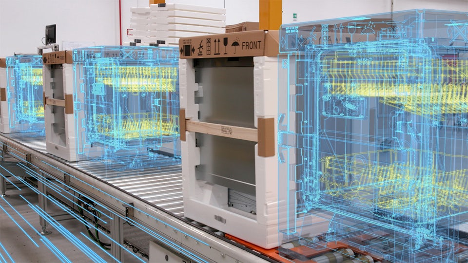
Innovation and collaborative, synchronized program management for new programs
Composites manufacturing processes are complex and specialized. Only by instituting consistent and repeatable manufacturing processes can a company achieve the goals of reducing composite product costs while enhancing quality and throughput. To do this, manufacturing engineers need an accurate and efficient way to consume the engineering product definition. This demands an automated link between the design, analysis, and manufacturing definitions and the systems used in production. Fibersim specifically addresses these challenges by providing an intelligent design-to-manufacturing composite product development solution that is fully integrated into commercial 3D CAD systems – resulting in products optimized for performance, cost, quality and throughput.
Manufacturing a composite part requires data in many different forms with varying requirements – from points in 3D space for laser projection, to clean 2D curves on specific DXF or IGES layers for flat pattern nesting, to 3D ply boundaries in machine coordinates for automated deposition. As the master of the complete digital composite definition, Fibersim can generate all of these outputs at the click of a button directly from the digital twin of the composite part. Additionally, all of these derivative datasets can be archived with revision control against the engineering master in Teamcenter, ensuring an efficient, error-free, design-to-manufacture workflow for composite parts.
With the Fiber Placement Interface module in the Fibersim portfolio, engineers can automatically generate fiber placement data files within their CAD software systems directly from the 3D model of a composite part. These files accurately represent part layup surfaces, ply definitions, ply orientation information, and the unique fiber placement entities to significantly increase engineering productivity, eliminate errors, and make it easy to accommodate changes and optimize designs. This module enables engineers to import path planning post-processing data, including course centerlines and boundary information, allowing users to validate that a manufactured part meets design requirements through review of the imported post-processing manufacturability data, (including fiber angle deviation, radius of curvature, roller height, and collision avoidance angle).
Flat pattern template generation for composites is a time consuming and error prone process left in large part up to trial and error. The Fibersim Flat Pattern Export module eliminates the bulk of work associated with this task through the reuse of engineered composite definition to automatically generate 2D flat pattern data files. These automatically generated files can then be efficiently imported into any common commercial nesting or automated cutting system. Existing attributes from the ply definition are included such as part name, ply name, material orientation and sequence, and markers used to assist in layup.
The Fibersim Laser Projection module automates the generation of data required for laser projection systems to significantly increase manufacturing productivity, reduce errors, and make it easy to update and maintain laser projection data. These data files automatically include ply names, boundaries, origins, orientations, material properties, and names. This data can then be used for layup and ply verification to identify issues at the earliest point in the manufacturing process.
With the Tape Laying Interface module, engineers can automatically generate tape laying data files within their CAD system directly from the 3D model of a composite part. This eliminates errors, significantly increases engineering productivity and makes it easy to accommodate changes and optimize designs.