
Tecnomatix 디지털 제조 소프트웨어
지금 바로 제조 및 프로세스를 디지털화하여 자동차, 항공기, 의료 기기부터 전자 제품, 소비재, 맥주에 이르기까지 혁신적인 아이디어를 획기적인 제품으로 실현하십시오.
Tecnomatix의 이점
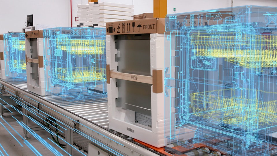
디지털 트윈 구축
로봇, 자동화, 자재 취급 시스템 및 인력을 포함하는 제조 프로세스의 포괄적인 디지털 트윈을 모델링, 시뮬레이션, 최적화하여 비즈니스 성과를 높이십시오.
유연성 향상
자동 또는 수동 생산 프로세스를 시뮬레이션 및 최적화하여 고급 제조 기술, 장비, 운영을 평가 및 구현하여 제조의 유연성을 확대하십시오.
혁신 속도 향상
현실적이고 몰입도 높은 고충실도 환경에서 물리 기반 모델링, 시뮬레이션 및 최적화 도구를 함께 사용하여 혁신 속도를 높이십시오.
인간 중심 제조
무엇을 통해 깊은 바다와 우주를 탐험할 수 있을까요? 무엇을 통해 안전하게 연결될 수 있을까요? 해답은 인간 중심 제조입니다.
인간 중심 제조를 통해 미래의 혁신을 현재의 획기적인 제품으로 실현할 수 있습니다. 첨단 로보틱스, 인공 지능과 같은 획기적인 기술을 사용하여 자체 구성 공장을 실현합니다. 제조의 미래를 살펴보십시오.
Tecnomatix 기능 소개
디지털 제조를 활용하여 현재 비즈니스를 개선하고 지속 가능성으로 미래에 대응하십시오.


Tecnomatix 블로그에서 최신 뉴스 알아보기
고객 성공사례
Electrolux
Case Study
Teamcenter, Simcenter and Tecnomatix help reduce development time by 20 to 30 percent
회사:Electrolux
업종:소비재 및 소매
위치:Stockholm, Sweden
Siemens Software:Simcenter 3D Solutions, Teamcenter, Tecnomatix
Tecnomatix 소프트웨어 제품군 살펴보기
디지털 제조 소프트웨어 제품을 사용하여 제조 프로세스와 장비를 최대한 활용하십시오.


