
Tecnomatixデジタル・マニュファクチャリング・ソフトウェア
車両、航空機、医療機器から電子機器、消費財、ビールに至るまで、製造とプロセスをデジタル化して、迅速に創造力豊かなアイデアを顧客向けの革新的な製品に変えることができます。
Tecnomatixを選ぶ理由
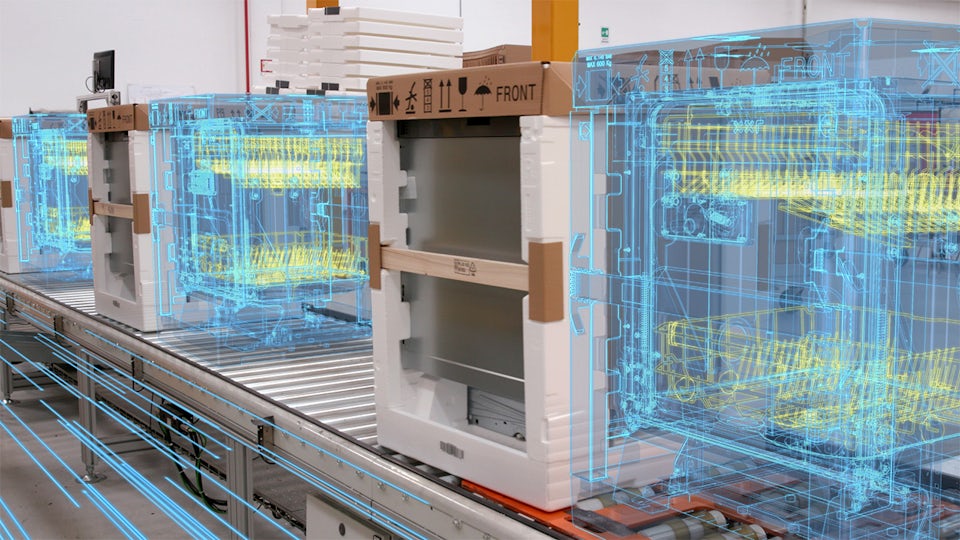
デジタルツインの構築
ロボット、自動化、材料管理システム、人など、製造プロセスの包括的なデジタルツインをモデリング、シミュレーション、最適化して、ビジネスのパフォーマンスを向上させます。
柔軟性の向上
自動または手動の生産プロセスのシミュレーションと最適化を使用して、高度な製造技術、機器、およびオペレーションを評価、実装し、より柔軟な製造を実現します。
イノベーションの迅速化
物理ベースのモデリング、シミュレーション、最適化ツールを備えた現実的で没入型の忠実度の高い環境を使用して、イノベーションを加速させます。
人間中心の製造
どのようにすれば私たちは海底と宇宙空間にいけるのでしょうか?どのようにすれば私たちの安全とつながりを保てるのでしょうか?人間中心の製造
人間中心の製造は、未来のイノベーションを革新的な製品に変えることができます。高度なロボット工学や人工知能などの画期的な技術を使用して、工場の自己組織化を実現します。未来の製造業を垣間見ることができます。
Tecnomatixの機能を確認する
デジタル・マニュファクチャリングを活用して、現在のビジネスを改善し、将来にわたってビジネスを維持できます。


Tecnomatixブログで最新情報を読む
ユーザー事例
Electrolux
Case Study
Teamcenter, Simcenter and Tecnomatix help reduce development time by 20 to 30 percent
会社:Electrolux
業界:コンシューマー製品 / リテール
開催場所:Stockholm, Sweden
シーメンスデジタルインダストリーズソフトウェア:Simcenter 3D Solutions, Teamcenter, Tecnomatix
Tecnomatixソフトウェア製品グループを確認する
デジタル・マニュファクチャリング・ソフトウェア製品を使用することで、製造プロセスと機器を最大限に活用できます。


