
Software di produzione digitale Tecnomatix
Digitalizza la produzione e i processi per trasformare le tue idee innovative (dai veicoli, agli aeromobili e ai dispositivi medici, all'elettronica, ai beni di consumo e alla birra) in prodotti all’avanguardia per i tuoi clienti, in questo momento.
Perché scegliere Tecnomatix?
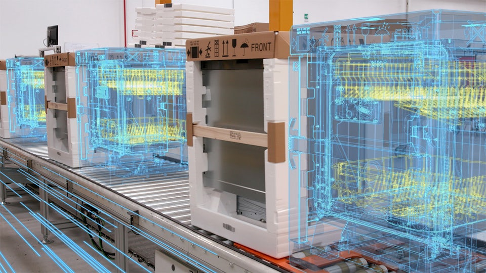
Costruisci il digital twin
Modella, simula e ottimizza un digital twin completo dei tuoi processi di produzione, inclusi robot, automazione, sistemi di movimentazione dei materiali e persone, per migliorare le prestazioni della tua azienda.
Aumenta la flessibilità
Utilizza la simulazione e l'ottimizzazione per i processi di produzione automatizzati o manuali per valutare e implementare tecniche, attrezzature e operazioni di produzione avanzate per una produzione più flessibile.
Innova più rapidamente
Utilizza un ambiente realistico, coinvolgente e ad alta fedeltà con strumenti di modellazione, simulazione e ottimizzazione basati sulla fisica per accelerare la tua innovazione.
La produzione incentrata sulle persone
Cosa ci porta sul fondo dell'oceano e nello spazio? Cosa ci tiene al sicuro e connessi? La produzione incentrata sulle persone.
La produzione incentrata sulle persone ti aiuta a trasformare le innovazioni di domani in prodotti all’avanguardia di oggi. L'utilizzo di tecnologie rivoluzionarie, come la robotica avanzata e l'intelligenza artificiale, rende le fabbriche auto-organizzate una realtà. Dai un'occhiata alla produzione di domani.
Esplora le funzionalità di Tecnomatix
Sfrutta la produzione digitale per migliorare il tuo business ora e sostenerlo in futuro.


Ricevi le ultime novità sul nostro blog Tecnomatix
Electrolux
Teamcenter, Simcenter and Tecnomatix help reduce development time by 20 to 30 percent
Azienda:Electrolux
Settore industriale:Beni di consumo e vendita al dettaglio
Sede:Stockholm, Sweden
Siemens Software:Simcenter 3D Solutions, Teamcenter, Tecnomatix
Esplora i gruppi di prodotti software Tecnomatix
Ottieni il massimo dai tuoi processi di produzione e dalle tue attrezzature utilizzando i prodotti software di produzione digitale.


