Siemens Digital Industries Software solution helps make it economically feasible for space agency to build composite crew module
One small step for Fibersim, one giant leap for advanced composites
NASA
NASA Engineering and Safety Center’s (NESC) mission is to perform value-added independent testing, analysis, and assessments of NASA’s highrisk projects to ensure safety and mission success. The NESC engages proactively to help NASA avoid future problems.
https://www.nasa.gov/offices/nesc- Headquarters:
- Hampton, Virginia, United States
- Products:
- Fibersim
- Industry Sector:
- Aerospace & defense
I don’t think it would be economical to construct something like the crew module without Fibersim.
NASA’s Langley Research Center
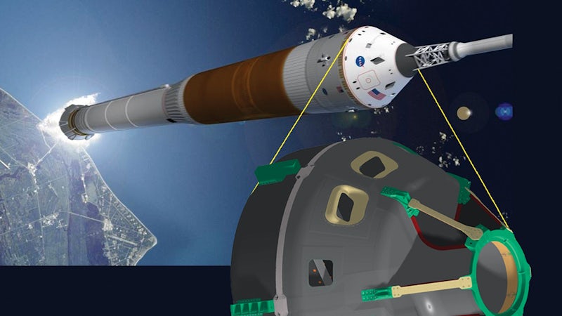
During NASA’s development of a composite crew module (CCM), it became obvious that use of the Fibersim™ portfolio of software for composites engineering from Siemens Digital Industries Software was vital to the project, enabling the team to significantly enhance its efforts in everything from design to fabrication. When it was all over, the team of NASA and industry engineers that collaborated on the design and manufacture of the crew module had a hard time imagining how they could have completed the task without Fibersim.
“We used Fibersim on just about every part of the CCM that was made of advanced composites,” says Mike Kirsch, CCM project manager for the NASA Engineering and Safety Center (NESC) at Langley Research Center in Hampton, Virginia, USA.
When NASA originally considered employing composites in manned spacecraft, it had conflicting considerations. On the one hand, there were concerns that composites might have an unacceptable leak rate and insufficient damage tolerance. On the other hand, composites offered lots of potential benefits, including reduced weight and lower lifecycle costs.
The most appealing aspect of applying composites to the crew module primary structure was a potential 10 to 15 percent reduction in weight on complex shapes compared to aluminum. In space travel, where every additional ounce of weight drives costs skyward, such a reduction in the weight of the crew module would have a profound effect on payload capacity and mission expense.
The potential of advanced composites was compelling, so NESC was charged by Mike Griffin (then NASA administrator) with putting together a team of government and industry structures experts to gain experience in making use of new composite construction and inspection technologies specifically for manned spaceflight structures.
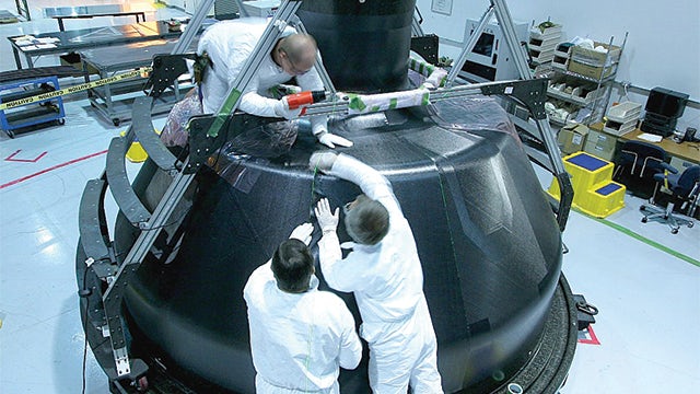
Pictured is the installation of ply segments during layup of the inner honeycomb sandwich skin at ATK in Iuka, Mississippi, USA. The composite plies are being laid up with the assistance of a laser projection system (as indicated by the feint green lines on the top and side of the capsule), which is driven by Fibersim software. The Laser Projection module in Fibersim enables engineers to automatically generate laser data files from within their computer-aided design (CAD) system directly from the 3D model of the composite part. This significantly increases engineering productivity, reduces errors and makes updating and maintaining laser projection data easy
Composites come of age at NASA
One of the primary goals of the program is to determine which composite materials are best suited for future NASA spacecraft. Kirsch is convinced that composite spacecraft will play a major role in NASA’s future missions. Composites are already being considered for use in structures where weight is critical, including lunar landers, habitation modules and launch vehicles.
Another goal of the project was to gain experience putting together an organizationally flat, collaborative and geographically dispersed team that could work together effectively. Kirsch said the collaborative effort was deemed a success. Nine of the ten NASA sites around the country as well as a number of significant aerospace companies, including ATK, Lockheed Martin and Northrop Grumman, contributed to the project.
The team considered nearly a dozen concepts and decided to make the CCM primary structure a stiffened honeycomb sandwich of carbon fiber. It is composed of upper and lower pressure shells spliced together to help meet the accelerated schedule and keep non-recurring costs under control (a mass-produced pressure shell would likely be one piece using multi-part extractable tooling). Further strengthening the shell are gussets, panels and various metallic fittings to distribute point loads. The lower shell is stiffened by the floor backbone, forming a unified structure which carries pressure and inertial loads via bending.
“Back-of-the-envelope calculations predicted that this concept would reduce the mass of the lower structure by 20 percent over a traditional ring frame pressure head design,” says Ian Fernandez, lower structure lead at the NASA Ames Research Center in Moffett Field, California, USA. “The concept was verified by finite element analysis and we went with it.”
Fernandez has worked on composite structures for over a decade. He used Fibersim during the Strategic Observatory for Infrared Astronomy (SOFIA) project, and to build a 10-foot aerodynamic aperture surface for a modified Boeing 747 commercial aircraft.
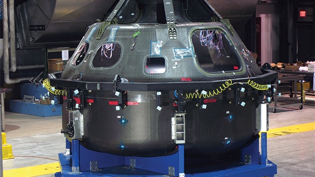
The composite crew module is shown during the assembly splice operation at ATK in Iuka, Mississippi, USA, prior to the installation of graphite epoxy doublers. The use of Fibersim helped NASA capitalize on the potential of composite materials by reducing risk, design and manufacturing costs as well as complexity and cycle times. The software has proven in production to increase engineering productivity and reduce development time, material waste, design revisions and tooling costs.
“Blown away” by Fibersim
“I saw Fibersim for the first time at the SAMPE Conference (Society for the Advancement of Material and Process Engineering) back in 1998 and was blown away,” says Fernandez. “The aperture was simple compared to the complexities of the crew module, but it didn’t make a difference to Fibersim.”
“It’s a big step to go from what’s in Pro/ENGINEER Wildfire to the manufacturing floor and then layup,” notes Kirsch. “The fidelity between what we saw in Pro/ENGINEER and how it translated in terms of wrinkles, ply angle and flat patterns were the true test of Fibersim.”
“One of the strengths of Fibersim is defining individual segments of plies, often referred to as flags,” says Fernandez. “It calculates how big and what shape the flags can be before they become too difficult to conform to the tool.” Fibersim can be used to display important features of a ply, such as splices, darts, boundaries, local coordinates, warp angle, etc. to help engineers build the best possible part.
“We paid special attention to minimizing overlaps in fit-up critical areas to prevent any issues down the road during assembly,” says Fernandez. Fibersim can then be used to calculate what shape the flat pattern needs to be, and export that data to manufacturing for the computer numerical control (CNC) cutting machine. Another critical capability of Fibersim is generating data to drive accurate laser projections of the flag boundary.
“Without this boundary projection on the tool, determining the location of the flags would be a painfully slow process and quality would be degraded,” explains Fernandez.
Fibersim was also used to produce laser projection files to help locate and trim the core (in place on the tool) and to create an inspection grid on the skins.
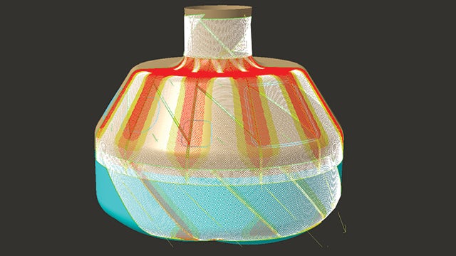
Pictured is a producibility simulation of the NASA composite crew module created using Fibersim. The white fibers indicate areas that fall within specification, while the yellow areas indicate mild deviation and the red areas indicate areas of significant deviation from specification. Fibersim enables users to understand what areas will present manufacturability issues prior to reaching the shop floor, saving a significant amount of time and resources.
Determining if composites have “The Right Stuff”
“I don’t think it would be economical to construct something like the crew module without Fibersim,” says Kirsch. “You could build a simplified version for the same price, but mass and quality would take a big hit, driving operational costs way up. For state-of-the-art applications like this – where every aspect is critical – Fibersim was the perfect solution.”
How will NASA decide if the CCM meets expectations? It will give it the old shake test. Testing will be performed on a static test rig that will apply force to critical parts of the CCM, simulating the stresses encountered during a mission.
If the results of the CCM project are positive, it is likely that there will be a composite manned spacecraft taking off sometime in the future. In fact, the project has already paid dividends: The developers of NASA’s Orion crew module (who are also using Fibersim) are applying lessons learned from the NESC CCM to composite aspects of their craft. The Orion structure consists of 40 percent composites by mass.
The main difference is that Orion’s pressure module is metallic, while NESC’s pressure module is composite.
The hope at NESC is that one day someone will be sitting in that module heading into space.
Don’t bet against it.
We used Fibersim on just about every part of the CCM that was made of advanced composites.
NASA’s Langley Research Center