1. Home

NX

Fibersim

Fibersim is a specialized software solution used in industries that rely on composite materials to design, simulate, and manufacture composite structures more efficiently and accurately.

Zoomed in visual of composite material, carbon fiber weave

Why Fibersim?

Fibersim enables part-specific design approaches for advanced composite structures. These approaches are specialized depending on the industry, whether automotive, aerospace, energy, or others where composites play a role.

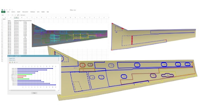
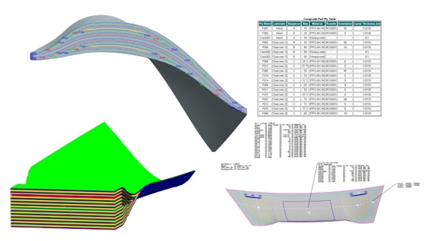
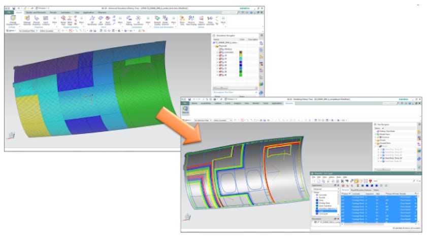
To be fully optimized, advanced composite parts require unique analysis, design and manufacturing workflows. Fibersim leads the industry in supporting specialized workflows for the development of advanced composites. It supports concurrent engineering where analysis and design are performed in the context of the manufacturing, which is key to developing the highest performance, lowest cost designs.

Advanced composites undergo extensive analysis and design iterations carefully considering a part’s unique weight implications. Fibersim features tight integration with Simcenter and other CAE systems, providing bi-directional updates between designers and analysts while taking manufacturing constraints into consideration.

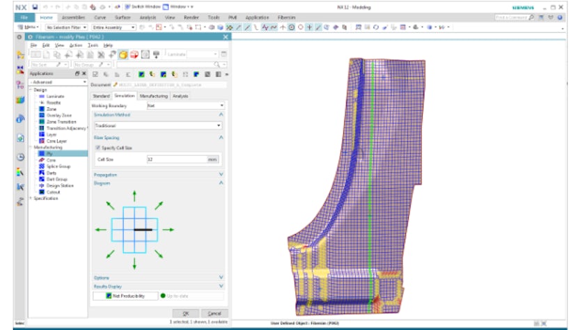
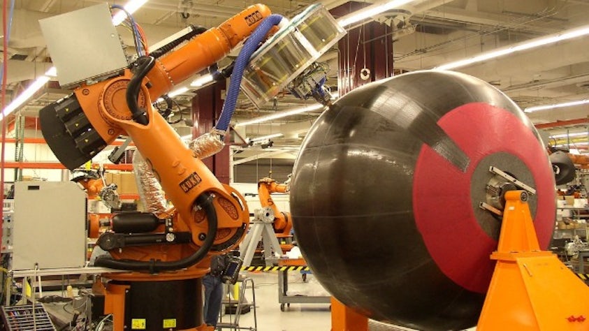
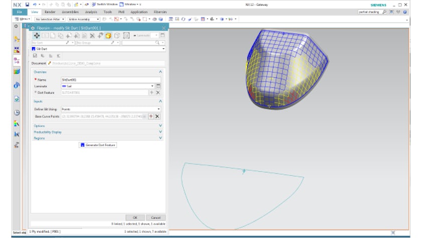
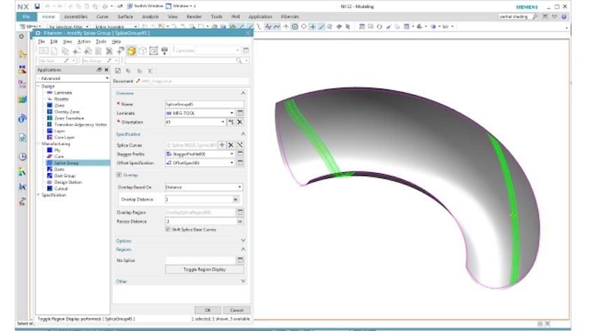
Design for advanced composite manufacturing is available as well. Whether the manufacturing process is hand laid, tape laid, fiber placed, or braided, Fibersim has the capabilities to ensure the design is fully manufacturable before design release.

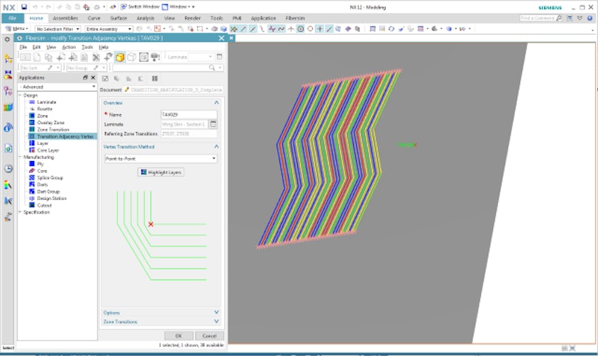
The open, multi-CAD architecture of Fibersim provides these specialized engineering capabilities in NX, CATIA and CREO. Fibersim also saves the detailed laminate structure of the composite design into Teamcenter to share across the enterprise.

Fibersim design and analysis features

Composites simulation driven design

Efficiently adapt to changes while providing an accurate simulation of the as-manufactured composite part. Using our capabilities as the hub for your composite part design allows for the efficient input of requirements from CAE to create a CAD digital twin that can rapidly react to changes in shape and specification, all while providing a window onto the shop floor to ensure the producibility of your design. Design rules provide powerful automation in the creation of ply boundaries from minimal geometry input. Additionally, advanced sorting, filtering and renaming capabilities provide efficient tools for navigating the complexity of modern composite parts.

Zone based composite data exchange between design and analysis

Composite design data verification

Engineering documentation brings visibility to the composite details during verification, including drop-off profiles, ply sequence order and ply materials. The Fibersim approach helps automate the creation of cross sections, annotations and core samples that are updatable as changes occur, ensuring the design is accurately reflected. Core sampling capabilities provide deeper details, such as ply thickness changes, fiber deviation, balance and symmetry, which are invaluable in ensuring product quality. Understanding laminate weight and cost is critical to making go/no-go decisions during verification. The software instantly provides the laminate weight and cost, including post cure processes, to provide the most accurate information during review.

Assembly relationships, such as packaging and clash detection, are an important aspect of design verification as well. Surface and solid representations are automatically created, allowing you to detect clashes between assembly components and ensure that packaging requirements are met.

Core samples and ply lists automatically generated for composite laminate

Detailed composite design definition

Whether you are designing a solid airfoil with Volume Fill capability, using Zone-based design to produce nested plies in a large structural component, or leveraging the unique Multi-Ply approach to automate a ply-based design, we have the optimal design methodology for your part type. Once authored, the complete composite definition can be leveraged throughout the enterprise, from flat patterns and laser-projected ply boundaries on the shop floor to 3D documentation for design reviews to accurate weights directly in Teamcenter.

Ply corner chamfering to manage zone transitions in composite design

Modern composite design with digital twin

Preliminary design

The bi-directional Analysis Interface provides an automated exchange of stress requirements into a CAD digital twin. Even before detailing the part with design rules, preliminary weights and space claim solids can be derived from the zone definition. Once the final ply boundaries have been defined, the true fiber orientations can be sent back to stress to be re-analyzed with the as-manufactured definition.

Product producibility simulation

The producibility simulation is a production-proven capability for accurate flat patterns and true fiber orientations. With the complex curvature and advanced materials of modern composites, specified orientations cannot be assumed and having a reliable simulation of the part producibility is critical to repeatable and high-performing parts. This also provides a preliminary look at path planning challenges for automated deposition.

Automatic zone to ply mapping to create detailed composite definitions
Industry leading material simulation methodologies show impacts on producibility and fiber orientations

Fibersim design and manufacturing features

Open architecture

The digital twin of a composite part only has value if it can be leveraged throughout the product lifecycle. Our open architecture provides access to best-in-class industry solutions to the complete digital definition of the composite part.

The HDF5-based CAE Exchange Format provides access to leading CAE tools. The Flat Pattern Export module provides optimized flat patterns for leading cutters and nesting packages. Laser Projection creates a true offset dataset that can be consumed directly by leading laser projection systems. Automated Fiber Placement and Tape Laying exports can be leveraged by leading path planning software for automated deposition.

All of these integrations are available regardless of the CAD system used to author the composite definition – whether NX Composites or Fibersim in NX, CATIA, or Creo – allowing OEMs and suppliers to work on their preferred platform for design.

Automate fiber placement machine lays carbon fiber for cryogenic fuel tank at NASA Marshall Space Flight Center

Composite manufacturing definition

While assessing part producibility is critical to avoiding costly re-work, most manufacturing processes require the incorporation of additional manufacturing details. 

For hand layup, these are built-in to the ply, with real-time feedback of different darting strategies, material width warnings and automated splice group assignment. For automated deposition, our advanced composite capabilities provide tools to account for minimum course limitations of specific machines and the staggering of origins for path planning. For forming and braiding processes, our advanced capabilities also offer tools to help designers assess part and process feasibility.

Once the details are captured, they can be leveraged directly by the shop floor via exports to flat pattern, laser projection and path planning software.

Producibility simulation showing corresponding flat pattern

Composite manufacturing definition detail

Resolving material deformation, deviation and fiber buckling before layup reduces iterations and increases manufacturing throughput. Our composite software does this with flexible, automated splicing and darting capabilities. Incorporating specifications, including staggered splicing, splice overlap, no-splice regions and no-dart regions, helps automate creation and ensures design and manufacturing requirements are met.

Ply splice management with splice groups for composite part

Composite manufacturing documentation and automation

Documenting a composite design for manufacture can be a tedious and error-prone process. By repurposing the composite design data already captured, the Documentation module can be used to automate the generation of accurate manufacturing plybooks, ply tables and 3D data.

Plybook page showing flat pattern and layup method for composite manufacturing operator

Related resources